
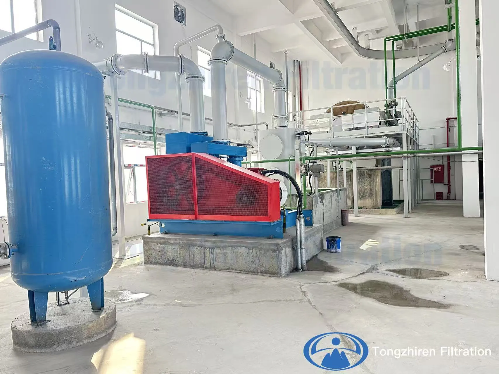
A vacuum disc filter station layout must accommodate the machine, its auxiliaries, the cake-handling equipment, and the space needed to operate and maintain them. A filter that fits between building columns may still be difficult to service if a sector cannot be removed or a drive cannot be lifted out.
Develop the layout around actual equipment connections and maintenance tasks. The result should show how material, water, people, and replacement components move through the station.
There is no universal floor-space allowance per square metre of filtration area. Required space depends on disc dimensions, the number of discs, auxiliary equipment, component-removal routes, access platforms, lifting arrangements, and downstream cake handling.
Request a general arrangement drawing showing operating dimensions and maintenance clearances. Review it in both plan and elevation before fixing building dimensions or routing permanent services.
Disc filters can provide substantial filtration area within a compact machine envelope. ANDRITZ also identifies component access and removal as features of its STARDISC design. These are separate considerations: compact equipment still needs room for the intended service procedure.
The machine envelope covers the physical equipment. Operating space allows people to inspect instruments, observe the process, and use designated access points. Maintenance space allows parts, tools, and lifting equipment to move through the station during servicing.
Draw all three on the layout. A permanent pipe can remain outside the machine envelope while blocking a maintenance route. Likewise, an open walkway does not prove that a large replacement component can pass through it.
Maintenance space may sometimes overlap an area used differently during production. Make that arrangement explicit and check how the area will be made available when needed.
The cake outlet connects the filter to a chute, conveyor, bin, or other handling system. Establish the receiving equipment's location before deciding the filter support elevation.
Review the cake's measured behavior and expected variation. A wet, sticky cake may need a different transfer arrangement from a cake that breaks and moves freely. Chute geometry and conveyor selection should follow the material assessment.
Ask the layout team to show:
where cake first contacts the receiving equipment;
how material spreads across the conveyor or into the bin;
access for inspecting the transfer;
space for removing replaceable chute sections;
how collected wash water reaches the intended drainage system.
Keep the receiving equipment's own maintenance requirements visible. Filter supports should not unintentionally obstruct conveyor belt replacement or access to a drive.
A cloth-covered vacuum disc filter may connect to vacuum pumps, gas-liquid separators, filtrate receivers and pumps, blowback equipment, and cloth-washing services. The exact arrangement depends on the selected design.
The concept of station-level planning is reflected in Metso's Filtration Plant Unit description, which addresses auxiliaries, pumping arrangements, pipe routes, and layout together. A complete plant package and an individual filter assembly can have very different boundaries.
Mark each auxiliary on the drawing with its service connections and access requirements. Then ask where a technician stands, where the component is removed, and how the replacement reaches that location.
A short line on a floor plan may conceal an awkward vertical rise, a low pocket, or a conflict with a platform. Review the slurry, filtrate, vacuum, cleaning-water, and drain routes in three dimensions.
The filter and vacuum-system suppliers should confirm the hydraulic arrangement. A pumped filtrate system and a gravity discharge arrangement do not necessarily require the same elevations or connection details.
For each significant line, show the connection location, supports, isolation points, and removable sections. Confirm whether a pipe must be disconnected to service the equipment beside it. If so, that work belongs in the maintenance plan.
Avoid assuming that nozzle position alone defines an acceptable pipe route. Supports, thermal movement where relevant, and loads on equipment connections need their own engineering review.
Select representative maintenance tasks before approving the layout. Use the supplier's procedure to trace each component from its installed position to a staging area outside the machine.
| Maintenance task | Space to demonstrate on the drawing |
|---|---|
| Sector or filter-cell replacement | Removal direction, handling space, and a route to the staging area |
| Rotary valve service | Access to fasteners and room to withdraw the specified parts |
| Drive replacement | Lifting approach and clearance around adjacent equipment |
| Filtrate pump service | Withdrawal path, disconnection access, and transport route |
| Spray assembly work | Tool access and space to remove the specified section |
These are layout review prompts. The actual component weights, removal distances, and methods must come from the selected equipment documentation.
An illustrative problem is a valve that requires horizontal withdrawal toward a wall. The machine itself may fit comfortably, yet the wall makes the specified service task impossible. Moving the filter or revising the access arrangement during design is simpler than discovering the obstruction after installation.
Where a maintenance procedure calls for lifting equipment, review the complete movement. Hook travel, lifting attachments, component height, and intervening structures all affect usable clearance.
Provide a staging location where removed components can be placed and replacement parts prepared. Identify the route between this area and the building entrance or workshop.
Ask for lifting and support loads from the supplier so the structural design uses the correct information. A drawing that shows a crane symbol without its required coverage leaves an important interface unresolved.
Operators need practical positions from which to read local instruments and inspect designated process points. Place sampling points where the sample can be collected according to the plant's procedure and represents the stream being measured.
Review the visibility of the cake discharge and the location of local controls. Check whether platforms, handrails, equipment, or pipework interfere with normal access or observation.
For moisture reporting, decide whether sampling represents cake at filter discharge or after downstream handling. That choice affects both the layout and the interpretation of performance data.
Identify where wash water, trough drainage, and routine spillage will go. Establish the collection destination and pumping arrangement where required.
Keep the drainage design consistent with the plant's water balance. Material-bearing drainage returned to the process is a different stream from clean service water. Its destination should be shown rather than left to installation decisions.
Access routes and component staging areas also need to remain usable during the work planned for them. Review cleanup and drainage around these spaces as part of the station design.
If another filter is planned, reserve its equipment position, maintenance space, transfer connection, and routes for services. Check the implications for shared pumps, conveyors, electrical supply, and controls.
If expansion is proposed through additional discs, ask the manufacturer to confirm that the particular design supports it. A modular product family does not mean every installed shaft, drive, trough, or foundation can be extended.
Show future equipment as a distinct layout revision or marked expansion envelope so it remains visible during later design changes.
Provide the proposed equipment selection, building plan and elevations, column locations, floor levels, receiving conveyor or bin position, available lifting arrangements, utility connections, and maintenance access routes.
Include the scope boundaries so each party knows which drawings it must supply. For installation verification after design is complete, refer to the separate vacuum disc filter commissioning checklist.
Contact Tongzhiren Filtration with your process requirements and proposed station drawing to discuss equipment dimensions and layout information for the selection review.
No. Floor area must be considered with elevations, auxiliaries, access, component removal, and cake-handling interfaces. The process duty must also be suitable.
No. Clearance depends on the machine and its service procedures. Use dimensions and removal instructions for the selected equipment.
The receiving arrangement influences the cake-transfer geometry and required elevation. Reviewing both together helps expose conflicts with structures and access.
Trace the complete removal and replacement of an actual component, including tools, lifting, movement past obstacles, and the staging position.