
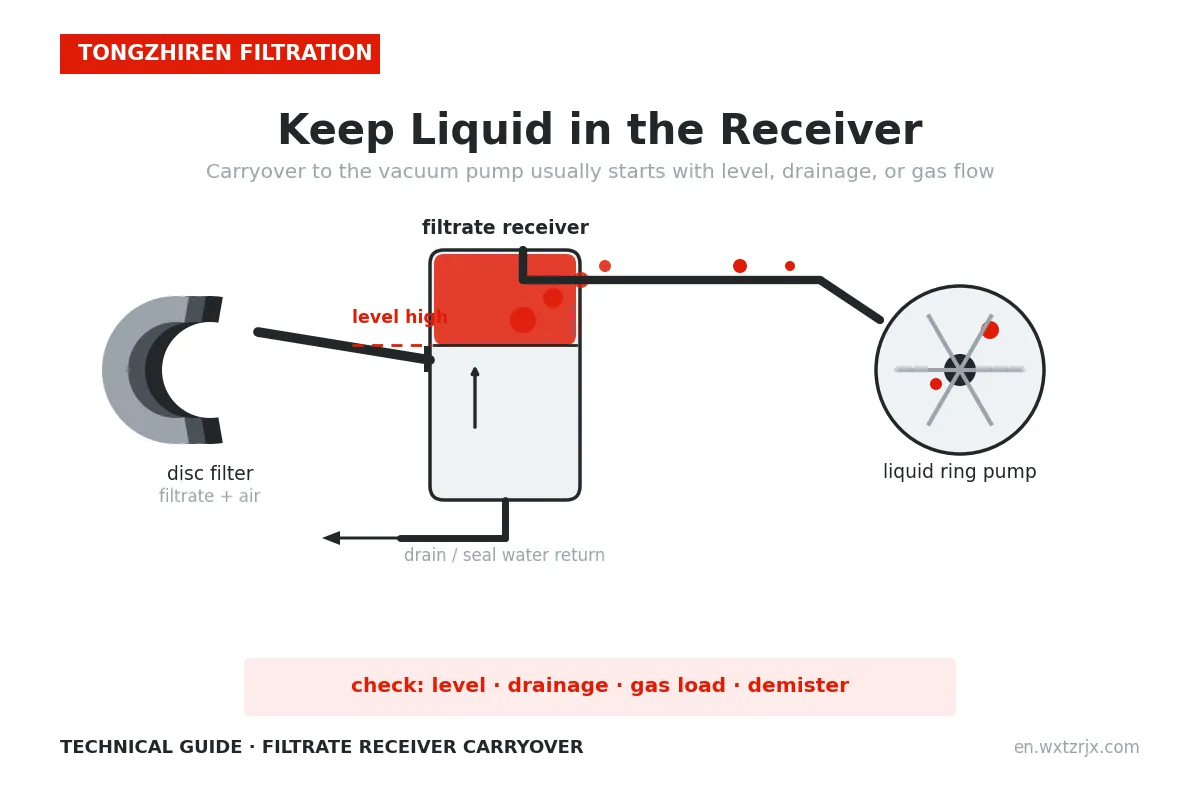
A filtrate receiver is part of the liquid-handling and vacuum arrangement in many filtration stations. Its job includes collecting separated liquid and allowing the gas stream to continue through the intended vacuum connection. When liquid is carried into a line intended primarily for gas, the station may experience unstable operation or expose downstream equipment to an unsuitable load.
Investigate the installed arrangement before changing a level setting or ordering a larger vessel. The receiver, drainage system, instruments, and gas path need to work together.
In a typical arrangement, the receiver accepts a gas-liquid stream from the filter, provides space for separation, and collects filtrate for removal. Gas continues toward the vacuum source while liquid leaves through the specified drainage or pumping system.
Not every filtration station uses the same configuration. The receiver upstream of a vacuum pump should also be distinguished from a liquid-ring pump's discharge separator, which separates operating liquid from the discharged gas. Busch describes the latter arrangement in its DOLPHIN VL system documentation.
Identify the vessel and trace its connections on the actual process drawing before discussing a fault.
Different vacuum technologies tolerate different inlet conditions. A liquid ring pump's ability to handle wet gas does not mean it can accept unlimited liquid flow or every contaminant in filtrate.
Busch's separator overview discusses protection against liquid and particulate contamination and notes that tolerance depends on pump technology. Confirm the permitted inlet conditions with the supplier of the installed equipment.
Carryover is therefore both a separation question and a system-compatibility question. Record what is being carried over, when it occurs, and where it is detected.
Compare receiver level with incoming liquid, drain or pump operation, and filter conditions. A high level may mean liquid enters faster than it is removed, but a faulty indication can lead to the same apparent symptom.
Check how the level is measured and what the signal controls. Compare independent indications where the design provides them. Use the approved inspection procedure; opening a receiver under vacuum is not an appropriate way to check its level.
Record alarms and commands as well as measured values. A pump-start command is different from evidence that filtrate is actually leaving the vessel.
More liquid storage volume may extend the time before a high-level condition, but it does not automatically provide adequate gas-liquid separation. Gas flow, inlet arrangement, liquid properties, operating pressure, and any internal separation components also matter.
Foam or droplets may be transported even when a level reading appears normal. Conversely, a well-designed separator can still carry liquid over if its drain fails and the liquid inventory rises too far.
A Busch liquid separator manual lists capacity, drainage, and internal components among carryover troubleshooting considerations. Its dimensions and settings apply to that accessory, not to an industrial filter receiver of a different design.
Liquid removal may use a pump, a gravity arrangement with sufficient liquid head, or another engineered system. The pressure difference between the receiver and the destination affects that arrangement.
An ordinary open drain to atmosphere cannot simply be assumed to work while maintaining vacuum. Likewise, a pump connected to a receiver must be selected for its actual suction conditions and discharge requirement.
Ask the supplier to confirm the liquid-removal design using vessel pressure, elevations, temperature, piping, and destination pressure. Do not apply a generic vessel height or pump rule without those conditions.
For a layout review, use the filtration-station layout guide and include both the receiver and its liquid destination.
The accumulation rate is the liquid entering minus the liquid leaving, with other relevant liquid sources included in the balance.
Suppose an illustrative receiver has 0.6 cubic metres of usable volume between its current level and a defined high-level threshold. Liquid enters at 12 cubic metres per hour but leaves at 8 cubic metres per hour. With constant flows, the net accumulation is 4 cubic metres per hour and the available volume is consumed in:
0.6 / 4 = 0.15 hours = 9 minutes
This is a simplified inventory example, not a safe response time or a sizing recommendation. Actual surge behavior, foam, instrument response, and protective actions require equipment-specific engineering.
The example explains why a small drain-capacity shortfall can become a recurring high-level event even if the vessel starts at a normal level.
| Observation | Next investigation |
|---|---|
| Level rises while the filtrate pump is commanded on | Confirm delivered flow and the pump's operating conditions |
| Carryover appears during a feed or wash surge | Compare the event with liquid inflow and available separation capacity |
| Carryover occurs without an indicated level rise | Check indication, foaming, entrainment, and internal condition |
| Vacuum changes after a drainage cycle | Review valve sequence and the intended pressure boundary |
| The symptom starts after modification | Compare the current arrangement with the approved drawing |
These are investigation directions. Confirm the cause before changing controls or equipment.
A receiver or connecting line can also create a vacuum-performance issue without obvious carryover. Compare pressure at useful locations and investigate restrictions using the system documentation.
Busch's vacuum-system troubleshooting guide identifies pipe geometry and obstructed components as possible sources of conductance losses. A pressure difference alone does not identify which component is responsible, but it helps locate the review.
Do not remove internal components or bypass protection to improve a gauge reading. Confirm their purpose and the supplier's approved corrective action.
The quotation should identify who selects the receiver, drain or filtrate pump, level instruments, protective functions, and connecting piping. Include normal and peak liquid flow, expected gas load, filtrate properties, and operating pressure.
Use the supplier scope checklist to avoid gaps between the filter package and vacuum package.
Contact Tongzhiren Filtration with the process drawing, vessel and pump details, level history, and event description to discuss the filter-station interfaces and the information needed for a technical review.
Not necessarily. Identify the inlet receiver and the pump's operating-liquid separator separately from the piping diagram.
No. Drainage, gas flow, foam, internal condition, and control behavior also need assessment.
No. Wet-gas capability is not an unlimited liquid-handling rating. Use the installed pump's approved conditions.
Time-aligned level, pressure, liquid-flow information, pump or valve status, and filter events are more useful than a single high-level photograph.